Converting to/from cubemapsWritten by Paul BourkeOriginal November 2003. Updated May 2006. Updated July 2016, July 2020 Added cube2sphere in November 2020. See also: Converting cubemaps to fisheye. The source code implementing the projections below is only available on request for a small fee. It includes a demo application and an invitation to convert an image of your choice to verify the code does what you seek. For more information please contact the author.
Converting from cubemaps to cylindrical projections Converting from cubemaps to cylindrical projectionsThe following discusses the transformation of a cubic environment map (90 degree perspective projections onto the face of a cube) into a cylindrical panoramic image. The motivation for this was the creation of cylindrical panoramic images from rendering software that didn't explicitly support panoramic creation. The software was scripted to create the 6 cubic images and this utility created the panoramic. Usage, updated July 2023
Usage: cube2pano [options] filemask
   filemask can contain %c which will substituted with each of [l,r,t,d,b,f]
   For example: "blah_%c.tga" or "%c_something.tga"
   Options
     -a n   sets antialiasing level, default = 2
     -v n   vertical field of view, default = 90
     -w n   sets the output image width, default = 4 * cube image width
     -x n   tilt angle (degrees), default: 0
     -y n   roll angle (degrees), default: 0
     -z n   pan angle (degrees), default: 0
     -c     enable top and bottom cap texture generation, default = off
     -s     split cylinder into 4 pieces, default = off
     -d     debug mode, default: off
File name conventions The names of the cubic maps are assumed to contain the letters 'f', 'l', 'r', 't', 'b', 'd' that indicate the face (front,left,right,top,back,down). The file mask needs to contain "%c" which specifies the view.
So for example the following cubic maps would be specified as %c_starmap.tga, Note the orientation convention for the cube faces. 
cube2cyl -v 90 
cube2cyl -v 120 
cube2cyl -v 150 
As the vertical field of view approaches 180 degree the representation as a cylindrical projection become increasingly inefficient. If a wide vertical field of view is required then perhaps one should be using spherical (equirectangular) projections, see later. ExampleCubic map 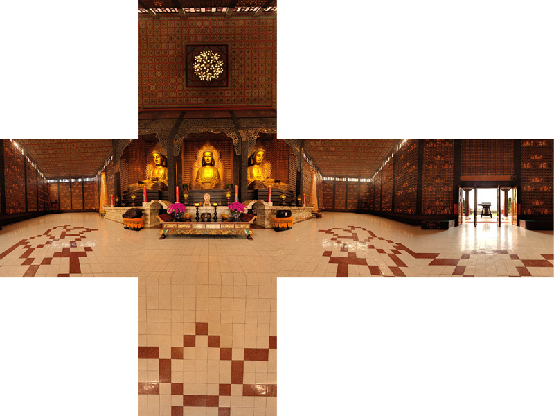
Cylindrical panoramic (90 degrees) 
Cylindrical panoramic (60 degrees) 
Cylindrical panoramic (120 degrees) 
Notes
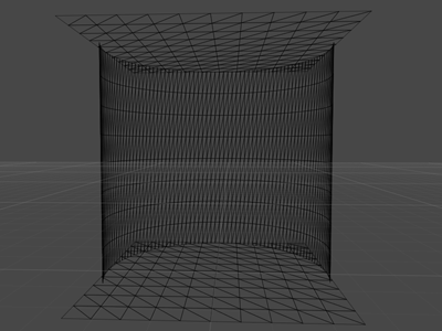
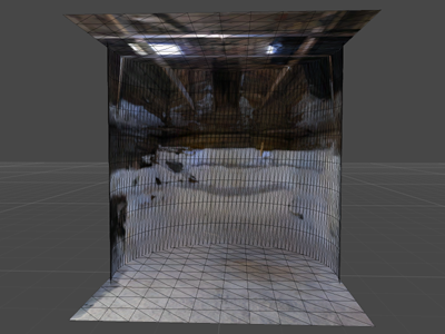
One can equally form the image textures for a top and bottom cap. The following is an example of such caps, in this case the vertical field of view is 90 degrees so the cylinder is cubic (diameter of 2 and height of 2 units). It should be noted that a relatively high degree of tessellation is required for the cylindrical mesh if the linear approximations of the edges is not to create seam artefacts.
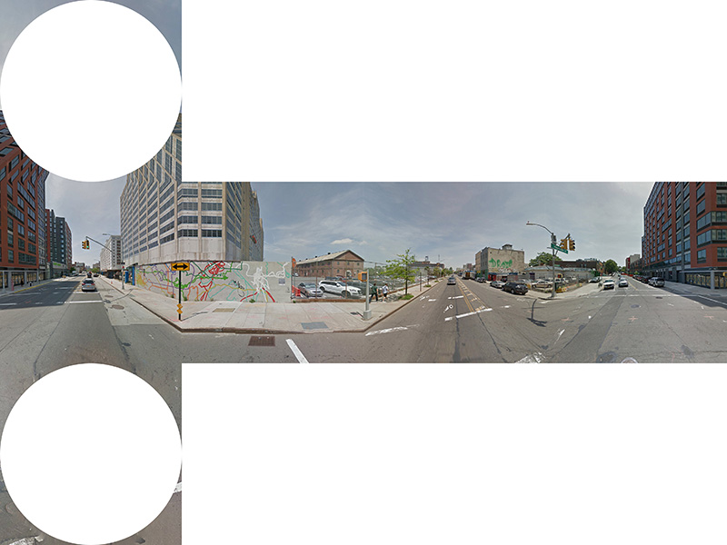
The aspect of the cylinder height to the width for an undistorted cylindrical view and for the two caps to match is tan(verticalFOV/2). Povray model to test seams of the top and bottom caps: cyltest.pov and cyltest.ini. Converting from cylindrical projections to cube mapsThe following maps a cylindrical projection onto the 6 faces of a cube map. In reality it takes any 2D image and treats it as it were a cylindrical projection, conceptually mapping the image onto a cylinder around the virtual camera and then projecting onto the cube faces. Indeed, it was originally developed for taking famous painting and wrapping them around the viewer in a virtual reality environment. Key to whether the image represents an actual cylindrical panorama or an arbitrary image is the correct computation of the vertical field of view so as to minimise any apparent distortion. If the following example the cylindrical panorama is exactly 90 degree vertical field of view, so in the cube maps the image extends to the midpoint of each f,r,l,b face. 
Usage: cyl2cube [options] cylindricalimage
Options
   -w n      output image size, default: outwidth/4
   -a n      antialiasing level, default: 2
   -x n      tilt angle (degrees), default: 0
   -y n      roll angle (degrees), default: 0
   -z n      pan angle (degrees), default: 0
   -d        debug mode, default: off
A PovRay scene that performs the same operation: cyl2cube.pov, cyl2cube.ini. Converting to and from 6 cubic environment maps and a spherical projectionIntroduction There are two common methods of representing environment maps, cubic and spherical, the later also known as equirectangular projections. In cubic maps the virtual camera is surrounded by a cube the 6 faces of which have an appropriate texture map. These texture maps are often created by imaging the scene with six 90 degree fov cameras giving a left, front, right, back, top, and bottom texture. In a spherical map the camera is surrounded by a sphere with a single spherically distorted texture. This document describes software that converts 6 cubic maps into a single spherical map, the reverse is also developed. ExampleAs an illustrative example the following 6 images are the textures placed on the cubic environment, they are arranged as an unfolded cube. Below that is the spherical texture map that would give the same appearance if applied as a texture to a sphere about the camera. Cubic map
Spherical (equirectangular) projection 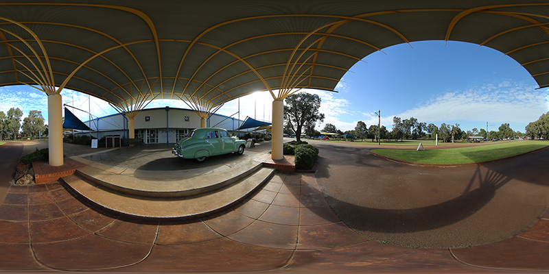
Algorithm The conversion process involves two main stages. The goal is to determine the best estimate of the colour at each pixel in the final spherical image given the 6 cubic texture images. The first stage is to calculate the polar coordinates corresponding to each pixel in the spherical image. The second stage is to use the polar coordinates to form a vector and find which face and which pixel on that face the vector (ray) strikes. In reality this process is repeated a number of times at slightly different positions in each pixel in the spherical image and an average is used in order to avoid aliasing effects. If the coordinates of the spherical image are (i,j) and the image has width "w" and height "h" then the normalised coordinates (x,y) each ranging from -1 to 1 are given by:
The polar coordinates theta and phi are derived from the normalised coordinates (x,y) below. theta ranges from 0 to 2 pi and phi ranges from -pi/2 (south pole) to pi/2 (north pole). Note there are two vertical relationships in common use, linear and spherical. In the former phi is linearly related to y, in the later there is a sine relationship.
The polar coordinates (theta,phi) are turned into a unit vector (view ray from the camera) as below. This assumes a right hand coordinate system, x to the right, y upwards, and z out of the page. The front view of the cubic map is looking from the origin along the positive z axis.
The intersection of this ray is now found with the faces of the cube. Once the intersection point is found the coordinate on the square face specifies the corresponding pixel and therefore colour associated with the ray. Mapping geometry
Usage: cube2sphere [options] filemask
   filemask should contain %c which will substituted with each of [l,r,t,d,b,f]
   For example: "blah_%c.tga" or "%c_something.tga"
Options
   -w n      sets the output image width, default = 4 * input image width
   -h n      sets the output image height, default = output image width / 2
   -x n      tilt angle (degrees), default: 0
   -y n      roll angle (degrees), default: 0
   -z n      pan angle (degrees), default: 0
  -w1 n      sub image position 1, default: 0
  -w2 n      sub image position 2, default: width
   -a n      sets antialiasing level, default = 2
   -raw n n  sets the dimensions for raw images file
   -e        enable eac (equalangular cubemap), default: off
   -s        use sine correction for vertical axis, default off
   -d        enable debug mode, default: off
Summary of the mathematics (pdf)
The reverse operation, namely converting a spherical (equirectangular) image into the 6 faces of a cube map is most commonly used for some navigable virtual environment solutions, but also to edit the north and south poles of spherical projections. UsageUsage: sphere2cube [options] spheretexture Options -w n output image size, default: spherewidth/4 -fb FaceBooks 3x2 composite image output (3x2), default: individual images -pb Paul Bourkes favourite image output (4x3), default: individual images -a n antialiasing level, default: 2 -x n tilt angle (degrees), default: 0 -y n roll angle (degrees), default: 0 -z n pan angle (degrees), default: 0 -raw n n spherical image dimensions for raw input file -e enable equiangular cubic mapping, default: off -d debug mode, default: off
It is fairly obvious that an equirectangular (spherical) projection is not an efficient way to store a 360x180 projection. This can be seen in the following image consisting of the faces of a cube and various test patterns. Note that the spheres and circular rings and all the same distance away, that is, they are lying on the surface of a sphere. The grid lies all in the same plane. Considering the faces with 9 spheres (one in the center, four towards the edges and four towards the corners) the size of the spheres (number of allocated pixels) increases towards the north and south pole. In the extreme case of a sphere at the poles there are many more pixels "wasted" representing that sphere. 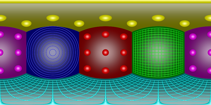
Cube maps are much better, the following is the representation of the same scene as above as a cubemap. The excesses at the poles has been solved and in general this is a much more even use of the available pixels. 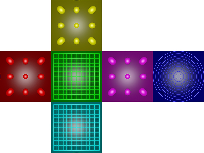
The reason for the stretching towards the corners of the cube can be illustrated in the figure below. Since the face of the cube is to be represented by pixels, all the same size, the rays into the scene (solid lines) get closer together as one moves from the center of the face towards the edges. 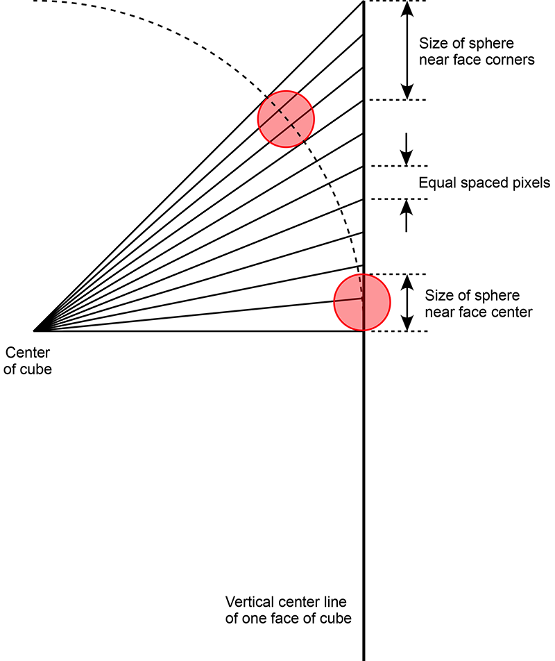
But still, it isn't entirely egalitarian. In particular notice that the spheres in the center of the faces are smaller that those towards the corners. This arises due to the tan() relationship between angle and distance along the cube faces. In essence more pixels are being used to represent the spheres towards the corners than in the center. This can be readily corrected for as is shown in the following. In this case instead of the sampling along the cube face being regular intervals across the face, the samples are spaced at even angle increments. 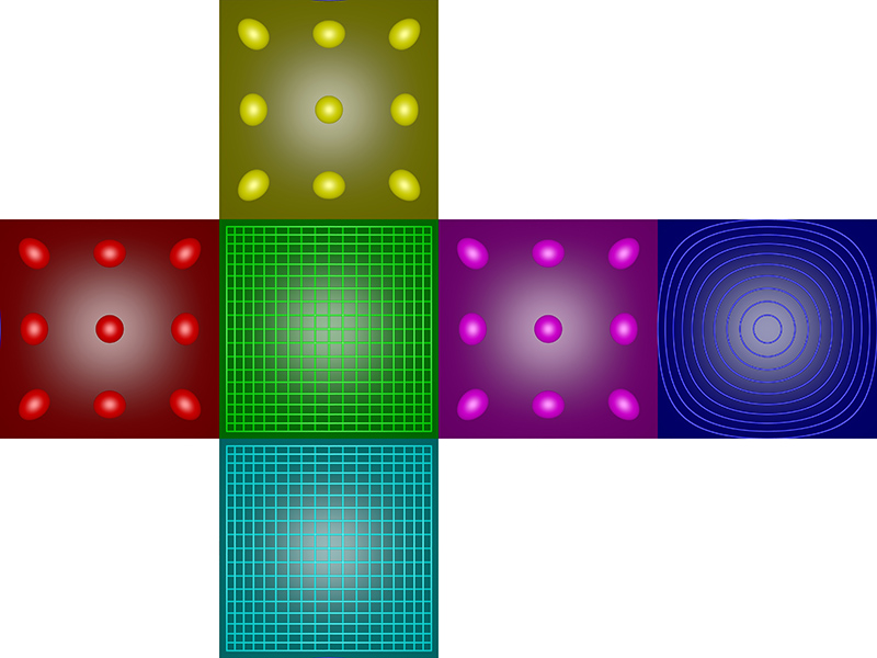
The situation is now a little more difficult to visualise. The solid ray lines in the following are now at equal angle steps. The dotted lines show where each ray line intersects the pixels, which still need to be equally spaced. Note this analysis is along a center line of a cube face, in reality the cube face is in 2 dimensions and elongation still occurs off this line towards the cube corners. 
A real world example follows, first image is the equirectangular projection, the second the standard non-equalangle cubemaps, and the last the equalangular cubemaps. Of course if these are used as the cubemap source then the interactive player needs to be aware of the mapping. The tan() and atan() functions required are readily added to the image mappings and/or GLSL shader. 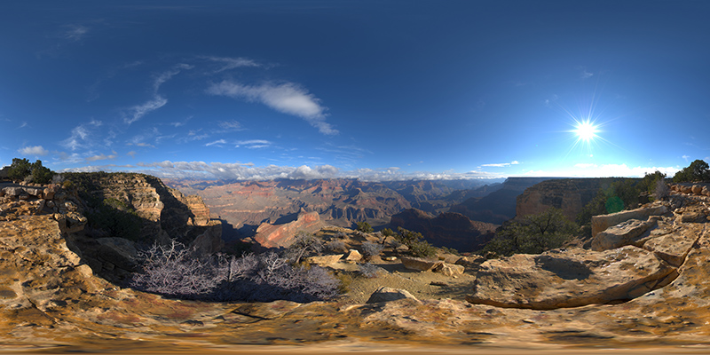
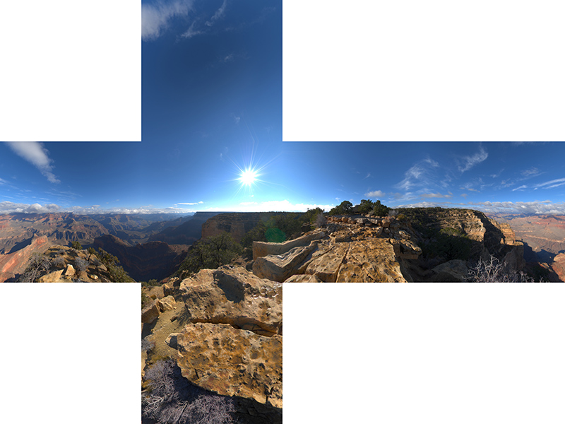

Interesting to download these two examples and overlay with 50% transparency, while the images look very different the edges still match perfectly. It can be seen the EAC version has a "zoom" effect on the interior of the cube faces, this results in a higher resolution there compared to the standard cube map. Implementation for Vuo (March 2020)

Extracting a perspective projection from cubemapsThis utility extracts a perspective projection from a set of 6 cube maps images. It is consistent with the conventions here: Converting an equirectangular image to a perspective projection and here: Converting to and from 6 cubic environment maps and a spherical projection As an example consider the 6 cube faces presented below. 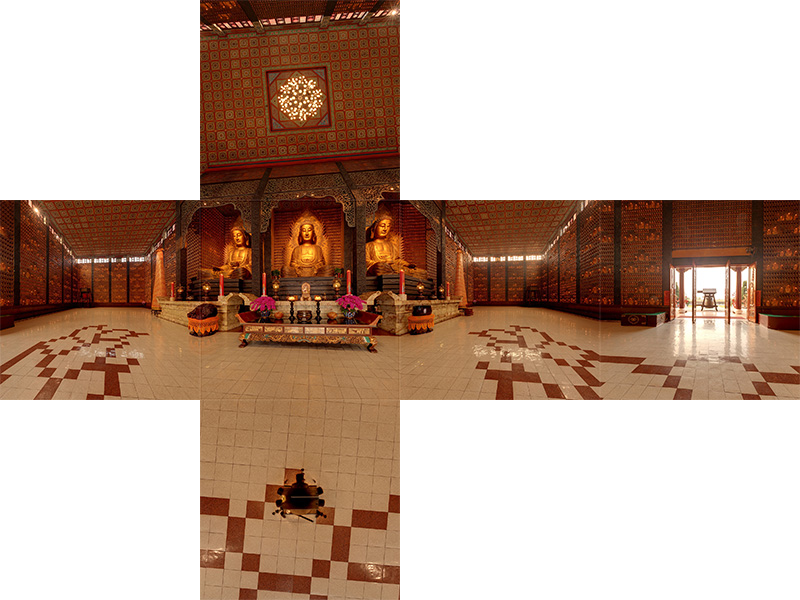
Some extracted mappings along with their corresponding command line options are shown below. All perspective views have a horizontal field of view of 100 degrees except the last zoomed example which has a 40 degree FOV. 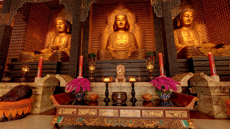
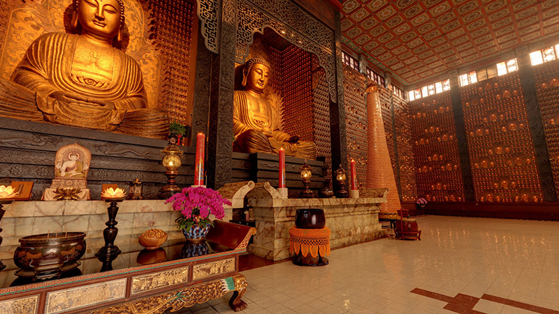

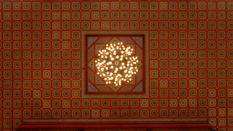
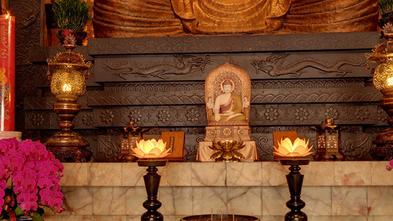
The command line options available are shown below. Usage: cube2persp [options] filemask filemask should contain %c which will substituted with each of [l,r,t,d,b,f] For example: "blah_%c.tga" or "%c_something.tga" Options -w n sets the output image width, default = 1920 -h n sets the output image height, default = 1080 -t n FOV of perspective (degrees), default = 100 -x n tilt angle (degrees), default: 0 -y n roll angle (degrees), default: 0 -z n pan angle (degrees), default: 0 -a n sets antialiasing level, default = 2 -e enable eac (equalangular cubemap), default: off -d enable debug mode, default: off
CubeRender (Historical interest only)Fast 360 degree 3D model exploration technique using 6 precomputed views mapped onto the interior faces of a cubeWritten by Paul Bourke January 1991
Image sets and other resources Introduction This report discusses an interesting technique that makes it possible to interactively view a high quality rendered environment from a single position using only 6 precomputed renderings. The technique has great potential for Architectural presentation of rendered scenes because it combines the ability to have fast (interactive) user control over the view direction while at the same time presenting very high quality renderings. The problemThe realism now possible with many rendering packages can be very attractive as a presentation tool. The considerable time required (often hours) to perform such renderings is not a concern because they are performed well ahead of the presentation. At the other end of the scale is the user controlled walk through experience where the user may choose to explore the environment at their leisure. In order to achieve 15 to 20 frames per second, only very simple models with crude rendering techniques can be attempted. There simply isn't computer hardware fast enough to perform high quality rendering of geometrically complicated models. The question then is what solutions exists between these two extremes? How can one present a 3D environment so that the user can explore it interactively and at the same time view it with a high degree of realism. A previous attemptOne approach, which was the topic of a previous report by myself, is to pre-compute many views at many positions within the 3D model. In the example I demonstrated, 8 views (45 degree steps) were created for each view position. The view positions were all at an average human eye height and lay on a regular grid aligned to fit on the interior of the environment, a room in the example. The correct view was determined from the database of precomputed views as the user moved from node to node and turned between view directions. In this solution both the movement between nodes and the changes in view direction at a node are discrete. Because of the potentially large number of images necessary both these discrete steps were quite large, 45 degrees for turning and 2 meters for movement. Even this resulted in weeks of rendering time as well as hundreds of megabytes of disk storage. This solutionThe approach taken here is to separate the exploration process into two activities, that of moving from one position to another in the scene and that of turning ones head while remaining at rest. Since an acceptable way of exploring an Architectural environment is to move to a position and then look around, this solution slows down the rate at which movement between positions can be achieved but it greatly speeds up the way the viewer can look about from a particular position. It is expected that, in implementations of this technique, while the movement between positions remains discrete, the changes in view direction can become continuous and unconstrained. Consider a viewing position within a 3D environment and make 6 renderings from this position. These 6 renderings are taken along each of the coordinate axes (positive and negative), they are each perspective views with a 90 degree camera field of view. Another way of imagining these 6 views is as the projection of the scene onto each of the faces of a unit cube centered at the view position. Once these 6 images have been generated, forget about the original model and create a new model which consists of only a unit cube centered at the origin with each of the 6 images applied as a texture (image map) to each internal face of the cube. The interesting part is that if the inside of the cube is viewed from the origin the seams of the cube cannot be seen (given that the cube is rendered with ambient light only). Indeed, as the view direction is changed what one sees is the same as what one would see with the same view direction in the original model. The advantages are that the "rendering" of the cube with textures can be done very quickly. Very little is needed in the rendering pipeline since there are no light sources, only ambient light and no reflected rays need to be computed. In fact many graphical engines have fast inbuilt texture mapping routines ideal for exactly this sort of operation. Example 1As an example, the following shows the 6 precomputed views from a computer based 3D model created by Matiu Carr. 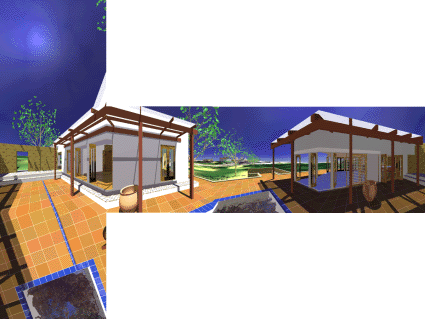
Figure 1
The views are arranged as if the cube they are applied to is folded out. An alternative method of folding out the cube is shown in figure 2 where the top and bottom faces are cut into quarters. 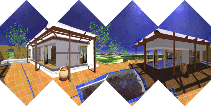
Figure 2
As can be seen there are no "gaps" although there are discontinuities at the seams. With some imagination you might believe that the discontinuities go away when the cube is folded back together. Two views from the interior of this cube are shown below on the left along with the same view on the right but this time with the edges of the cube shown.
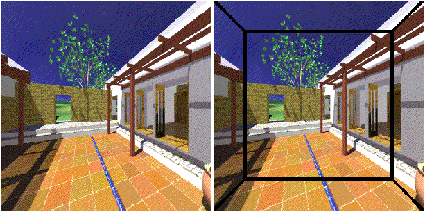
Figure 3
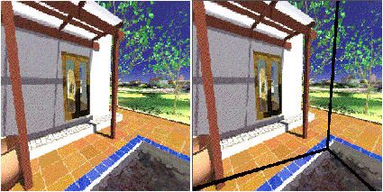
Figure 4
Looking at the images on the left, it is hard to imagine that you are viewing only the walls of a cube with murals painted on them. It is quite easy to imagine the painted walls when the edges of the cube are visible as in the images on the right. Here is a movie generated using the approach described above. (Raw images) Example 2 Model by Bill Rattenbury. (Raw images)
 Figure 5 - The folded out cube.
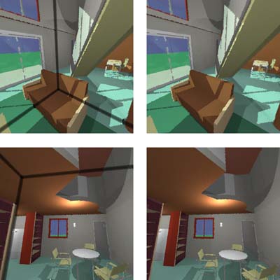 Figure 6 - The views on the left have the edges shown.
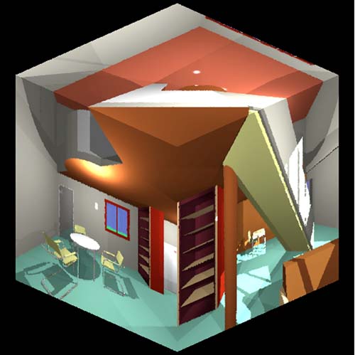 Figure 7 - Here is the cube viewed from the outside.
If you have Geomview and texture capabilities then the following 6 OOGL files will allow experimentation. Be sure to locate the camera at the origin [W]reset and just use the [o]rbit tool. A Macintosh viewer was written for evaluation purposes. It displayed the view from any user chosen view direction as well as giving the user control over the camera field of view and window size. The camera view direction can be entered directly as a vector or the left-right and up-down arrow keys will rotate the view direction in the horizontal or vertical plane respectively given an user specified angle increment. The viewer can also be used to view user generated environments given that the user can create the 6 precomputed views correctly. Examples of six precomputed view images are supplied with the Macintosh viewer as PICT files. The orientation of the 6 views with respect to each other must match the example in figure 1, this orientation is shown explicitly in the following cube mapping diagram. 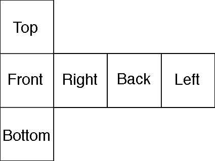 Figure 8 (Raw images)
The Macintosh viewer had the additional ability to show where the edges of the cube are, this is nice for demonstration purposes and was employed to generate the images shown in this document. POVRAY Example Raw images, POVRAY scene, POVRAY ini
The following example was created by Joseph Strout and demonstrates how the 6 views might be created using POVRAY. 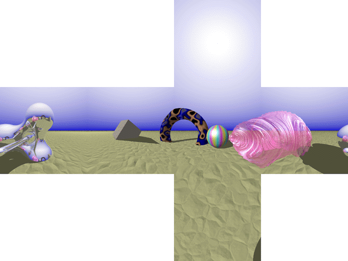
Figure 9
If you are using Radiance then the next two appendices contain the code necessary to create the appropriate texture mapped cube from a position within your favourite Radiance model. They are also provided with this document as two scripts MAKE6 and MAP6. Your use of these for a Radiance model called "mymodel.rad" looking from position (x,y,z) might be something like this, of course you will need to substitute your favourite or necessary options for the first two steps. oconv mymodel.rad > mymodel.oct make6 x y z mymodel map6 x y z | oconv - > x_y_z.oct rview -av 1 1 1 -ab 0 -ps 1 -dr 0 -lr 0 \ -vh 90 -vv 90 -vp 0 0 0 x_y_z.oct The following are the Radiance rpict calls required to create the 6 views from one view position. The important thing here are the up vectors for the top and bottom views so that the mapping onto the cube works correctly later on.
#
# Call this with four parameters
# The first three are the camera position coordinates
# The last is the oct file name (.oct assumed)
#
rpict -vp $1 $2 $3 -vd 1 0 0 -vh 90 -vv 90 \
      -av .1 .1 .1 \
      -x 300 -y 300 \
      $4.oct > $1_$2_$3_p+100.pic
rpict -vp $1 $2 $3 -vd -1 0 0 -vh 90 -vv 90 \
      -av .1 .1 .1 \
      -x 300 -y 300 \
      $4.oct > $1_$2_$3_p-100.pic
rpict -vp $1 $2 $3 -vd 0 1 0 -vh 90 -vv 90 \
      -av .1 .1 .1 \
      -x 300 -y 300 \
      $4.oct > $1_$2_$3_p0+10.pic
rpict -vp $1 $2 $3 -vd 0 -1 0 -vh 90 -vv 90 \
      -av .1 .1 .1 \
      -x 300 -y 300 \
      $4.oct > $1_$2_$3_p0-10.pic
rpict -vp $1 $2 $3 -vd 0 0 1 -vu 0 1 0 -vh 90 -vv 90 \
      -av .1 .1 .1 \
      -x 300 -y 300 \
      $4.oct > $1_$2_$3_p00+1.pic
rpict -vp $1 $2 $3 -vd 0 0 -1 -vu 0 1 0 -vh 90 -vv 90 \
      -av .1 .1 .1 \
      -x 300 -y 300 \
      $4.oct > $1_$2_$3_p00-1.pic
The following is the Radiance model of a cube with 6 views mapped on as colourpicts. Replace $1, $2, and $3 with the coordinates of your view position. It is this model which is rendered using rview or rpict, remembering that the view position should be (0,0,0) and the ambient light level needs to be high since there are no light sources.
void plastic flat
0 0
5 1 1 1 0 0
flat colorpict top
13 red green blue $1_$2_$3_p00+1.pic picture.cal pic_u pic_v
   -t -.5 -.5 0 -ry 180
0 0
flat colorpict bottom
11 red green blue $1_$2_$3_p00-1.pic picture.cal pic_u pic_v
   -t -.5 -.5 0
0 0
flat colorpict left
15 red green blue $1_$2_$3_p-100.pic picture.cal pic_u pic_v
   -t -.5 -.5 0 -rz 90 -ry 90
0 0
flat colorpict right
15 red green blue $1_$2_$3_p+100.pic picture.cal pic_u pic_v
   -t -.5 -.5 0 -rz -90 -ry -90
0 0
flat colorpict back
13 red green blue $1_$2_$3_p0+10.pic picture.cal pic_u pic_v
   -t -.5 -.5 0 -rx 90
0 0
flat colorpict front
15 red green blue $1_$2_$3_p0-10.pic picture.cal pic_u pic_v
   -t -.5 -.5 0 -rz 180 -rx -90
0 0
top polygon p1
0 0 12         -0.5               -0.5                0.5
               -0.5                0.5                0.5
                0.5                0.5                0.5
                0.5               -0.5                0.5
bottom polygon p2
0 0 12         -0.5               -0.5               -0.5
                0.5               -0.5               -0.5
                0.5                0.5               -0.5
               -0.5                0.5               -0.5
back polygon p3
0 0 12          0.5                0.5               -0.5
                0.5                0.5                0.5
               -0.5                0.5                0.5
               -0.5                0.5               -0.5
front polygon p4
0 0 12          0.5               -0.5               -0.5
               -0.5               -0.5               -0.5
               -0.5               -0.5                0.5
                0.5               -0.5                0.5
left polygon p5
0 0 12         -0.5               -0.5               -0.5
               -0.5                0.5               -0.5
               -0.5                0.5                0.5
               -0.5               -0.5                0.5
right polygon p6
0 0 12          0.5               -0.5               -0.5
                0.5               -0.5                0.5
                0.5                0.5                0.5
                0.5                0.5               -0.5
VRML Example
A VRML example, a text version, the raw images. For this to function properly your VRML player must support the following
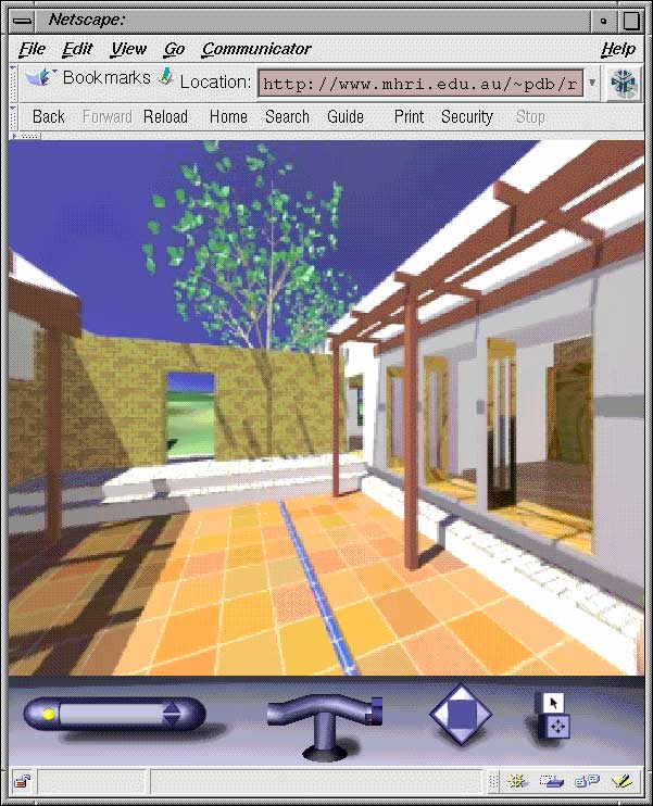
OpenGL is ideally suited to employing this technique as long as your OpenGL implementation has good texture mapping support. It is simply necessary to create the 6 faces of a cube specifying the texture coordinates and map the six images onto the faces appropriately. The source code to a simple OpenGL program that implements this technique along with 6 example textures is provided here. To compile it you will need to have the GL libraries as well as the GLUT libraries correctly installed. The "usage" for the viewer supplied is as follows, note the construction line toggle which is nice for showing people where the edges of the cube actually are.
Usage:    cuberender -x nnn -y nnn [-h] [-f] [-c]
      -x nnn   width of the images, required
      -y nnn   height of the images, required
          -h   this text
          -f   full screen
          -c   show construction lines
Key Strokes
  arrow keys   rotate left/right/up/down
  left mouse   rotate left/right/up/down
middle mouse   roll
 right mouse   menus
         <,>   decrease, increase field of view
           c   toggle construction lines
           q   quit
The example images provided here are 512 square, using a 4D51T card in a Dec Alpha this could be rotated at around 10 frames per second. Antialising
The code provided above uses GL_NEAREST in the calls This means that the textures are sampled at their centers and this can lead to aliasing artefacts. One way around this is to use GL_LINEAR instead in which case a 2x2 average is formed, however this leads to the need for special handling at the edges. OpenGL provides support for this but it means that you need to create textures that have a 1 pixel border where the border has the appropriate pixels from the adjacent faces. So the calls would change as followsglTexImage2D(GL_TEXTURE_2D,0,4,w+2,h+2,0,GL_RGBA,GL_UNSIGNED_BYTE,bottom); becomes glTexImage2D(GL_TEXTURE_2D,0,4,w+2,h+2,1,GL_RGBA,GL_UNSIGNED_BYTE,bottom); and glTexParameterf(GL_TEXTURE_2D,GL_TEXTURE_MIN_FILTER,GL_NEAREST); glTexParameterf(GL_TEXTURE_2D,GL_TEXTURE_MAG_FILTER,GL_NEAREST); become glTexParameterf(GL_TEXTURE_2D,GL_TEXTURE_MIN_FILTER,GL_LINEAR); glTexParameterf(GL_TEXTURE_2D,GL_TEXTURE_MAG_FILTER,GL_LINEAR); Comparison between CubeView and Apple QuickTime VR The characteristics are ordered in three sections, those which are clearly in CubeViews favour, those for which there is little difference, and finally those in QuickTimeVR's favour. Most of the items in QuickTime VR's favour arise simply from a lack of work being done to refine this technique, they are not inherent to the technique itself. Attribute CubeView QuickTime VR --------------------------------------------------------------------------- Full 360 vertical viewing Yes No Image quality Excellent Lossy compression Ease of scene generation Very easy More difficult Multiplatform scene generation Yes Maybe one day Distortion None Some Full camera attribute control Yes Not yet - - - - - - - - - - - - - - - - - - - - - - - - - - - - - - - - - - - - - - Full 360 horizontal viewing Yes Yes Based on precomputed information Yes Yes Suitable for computer generated scenes Yes Yes File sizes Similar Similar - - - - - - - - - - - - - - - - - - - - - - - - - - - - - - - - - - - - - - Multiplatform playback support Could be Yes Fast playback (interactive) Needs work Yes Multiple nodes Needs work Yes Object nodes and views Needs work Yes Suitable for photographic scenes Difficult Yes --------------------------------------------------------------------------- References Greene, N. (1986). Environment Mapping and Other Applications of World Projections. IEEE Computer Graphics and Applications, November 1986 (p. 21-29).
|
